- Introduction and Notes
- Tools/Materials Required:
- Instructions
- Step 1 – Prep Rollers part 1
- Step 2 – Prep Rollers part 2
- Step 3 – Attach Roller Bar
- Step 4 – Attach Cowls
- Step 5 – Insert 3DoT Springs
- Step 6 – Attach Sponsons
- Step 7 – Attach Idler arm
- Step 8 – Adjust Idler arm
- Step 9 – Prep Nose Cone part 1
- Step 10 – Prep Nose Cone part 2
- Step 11 – Attach Side Panels to Top/Bottom Panels
- Step 12 – Attach Nose Cone
- Step 13 – Insert Roller Forks
- Step 14 – Insert Bearings into idler wheels
- Step 15 – Insert Bearing Clips
- Step 16 – Attach Idler wheels
- Step 17 – Insert Motors
- Step 18 – Prep Drive Wheels
- Step 18 – Attach Drive Wheels
- Step 19 – Glue Magnets
- Step 20 – Add on 3DoT, Top and Tracks
- Chain Link Tracks
- Next
Introduction and Notes
Hello and congratulations on getting your Goliath and 3DoT! What follows are step-by-step instructions on how to assemble the kit. Some notes:
- Don’t worry if you have hardware parts left. Each kit was packed with one or two extra pieces of each part of hardware, just in case.
- The Goliath parts have been sanded and coated with two thin layers of spray paint. This is intended to let you paint on your own details, grime and decals.
- We are constantly learning more as we continue to create. If you notice any errors, or have suggestions on how we can do things better or easier, please share your experience with us.
Tools/Materials Required:
- 2mm Hex Key (Included in kit)
- 1.5mm Hex Key (Included in kit)
- #2 Philips Screwdriver
- T6 Screwdriver (Or small flat head, 1/16 tip works well)
- Small Tube of Superglue
Not on the list, but definitely recommended is a pair of tweezers. Some fine tip ESD tweezers are a must-have for other electronics projects so I would definitely consider getting some sooner or later.
Instructions
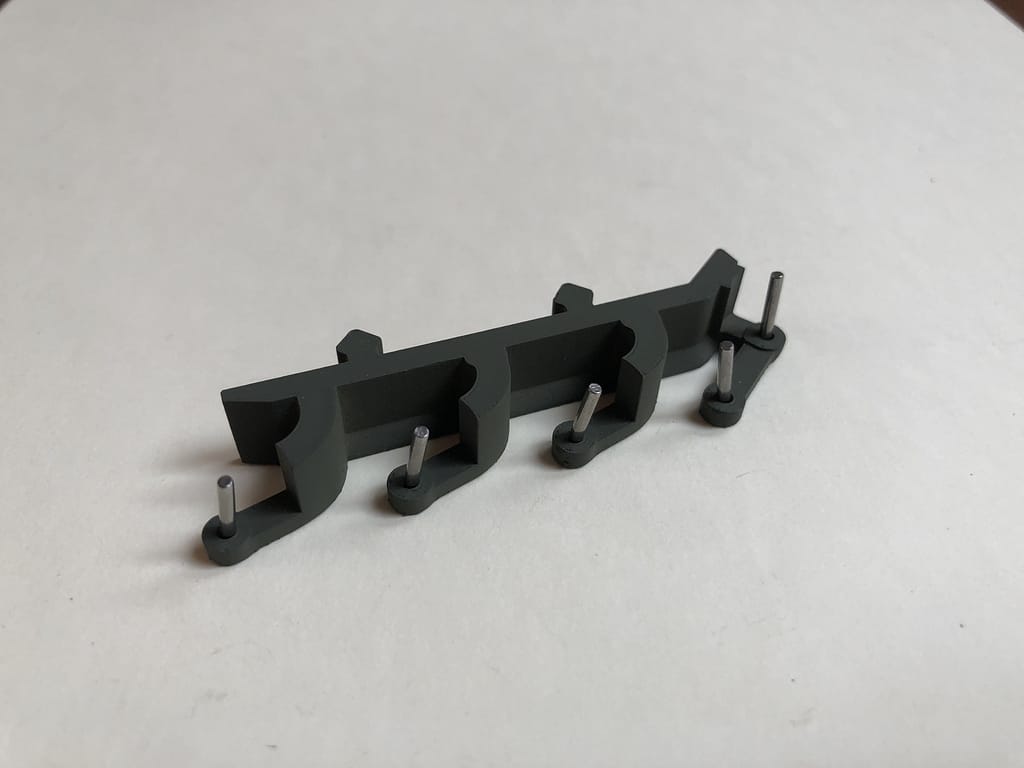
Step 1 – Prep Rollers part 1
The bars that will hold the roller wheels are split into two parts, inner and outer. Each is marked L (left) or R (right). Find the matching inner and outer pieces for L and R and place the small metal dowel pins into the larger (outer) pieces.
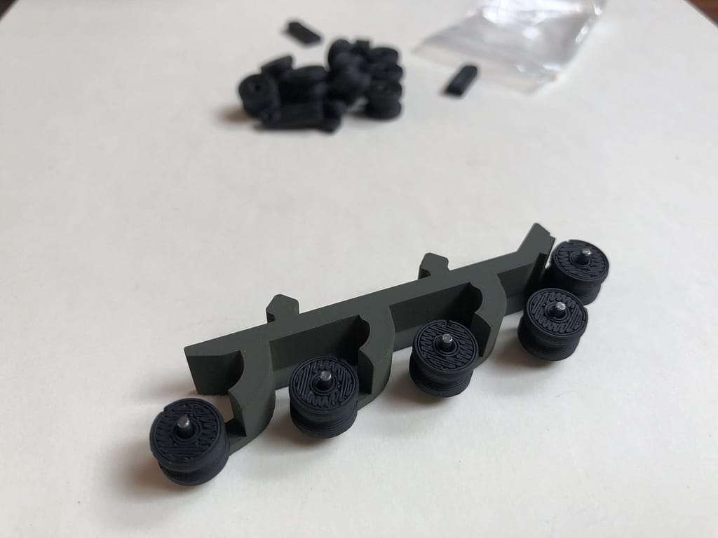
Step 2 – Prep Rollers part 2
Place the rollers on the dowel pins.
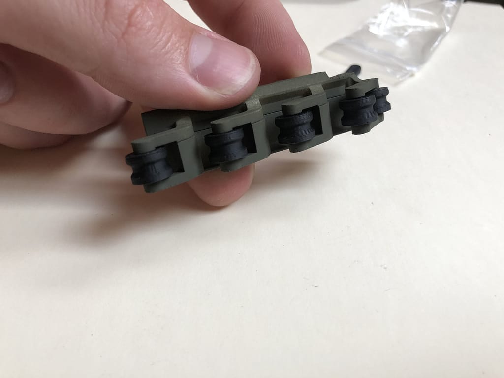
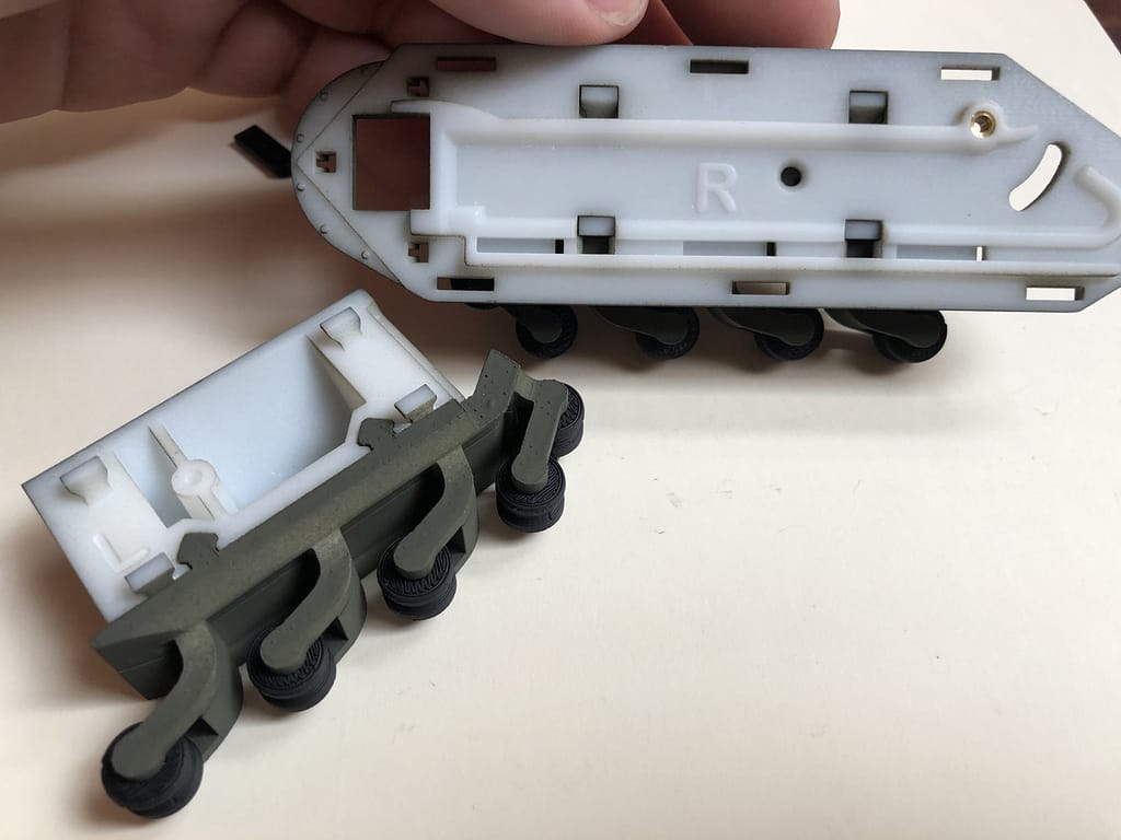
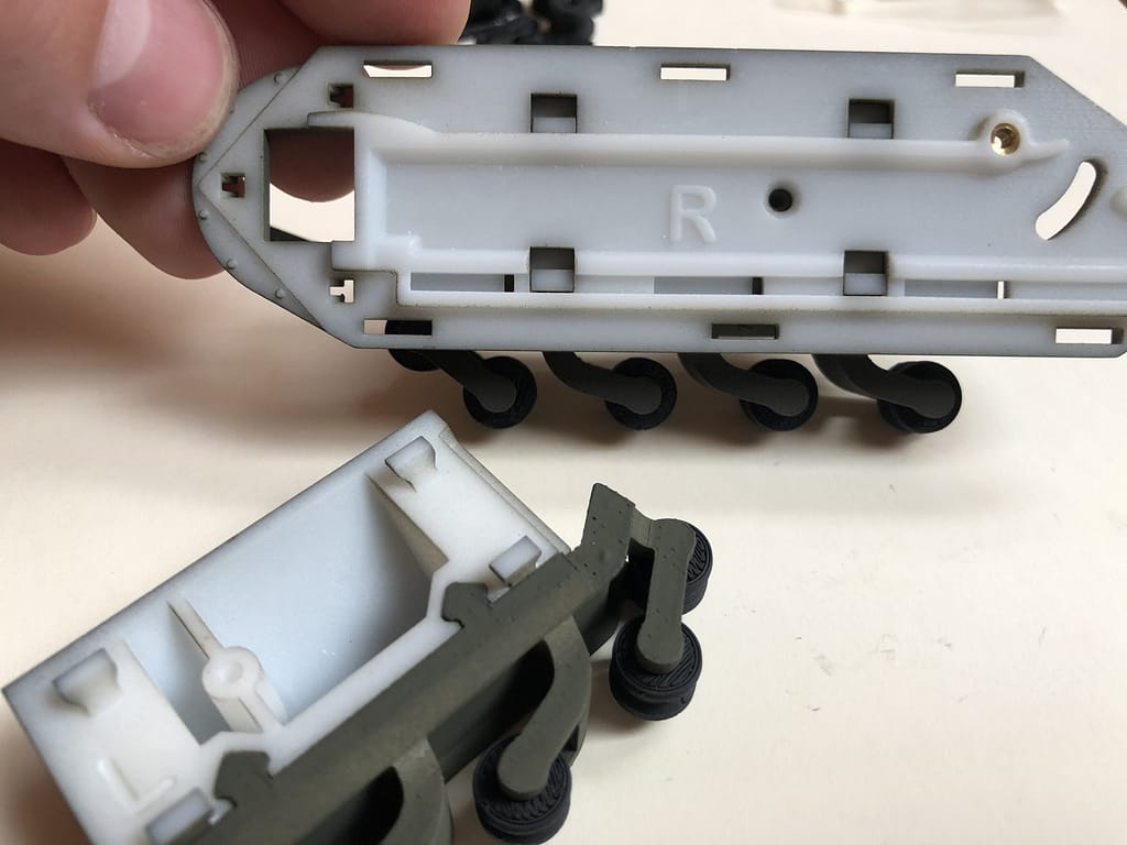
Step 3 – Attach Roller Bar
Squeeze on the inner part of the roller bar and slide it into the matching L or R sponson (Yes, that’s real word. I only just learned it too).
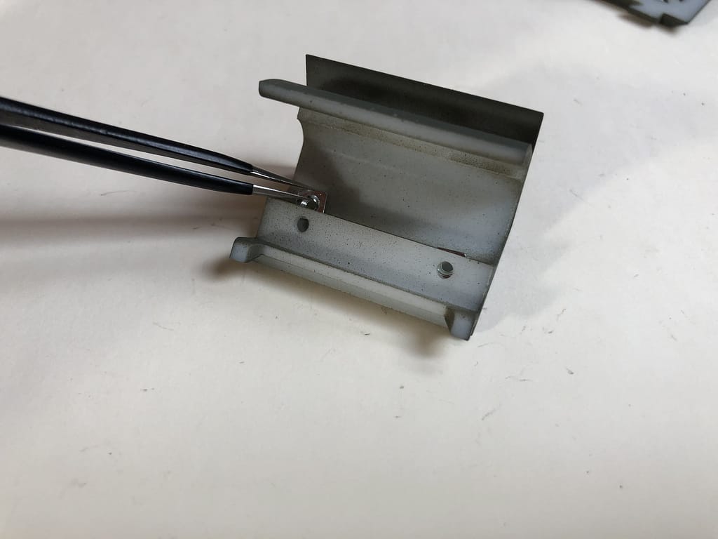
Step 4 – Attach Cowls
Clip the side cowls (another new word I learned from Jeff) onto the side panels. Again, each is labeled L and R. Make sure the L cowl clips onto the L side panel.
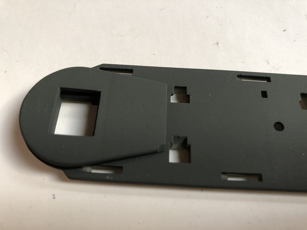
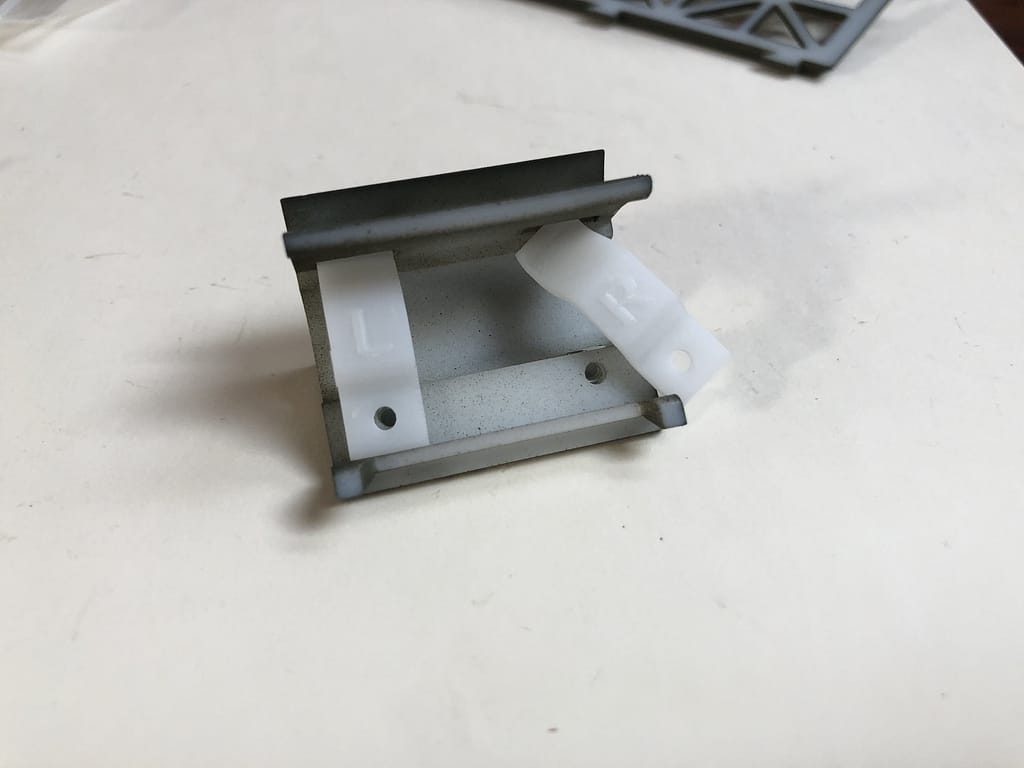
Step 5 – Insert 3DoT Springs
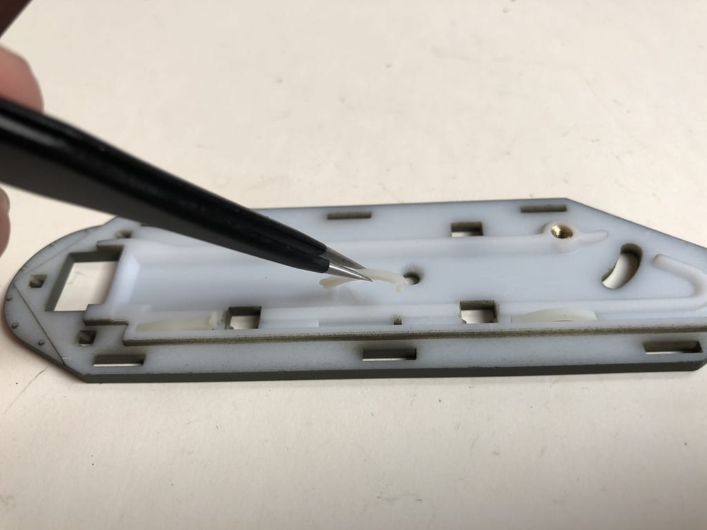
Push in the soft nylon clips into the other side of the side panel. The curved pieces act like springs to hold the 3DoT in tightly, but still allow it to slide in and out easily.
The pieces with a little hook on them are intended to stop the 3DoT from sliding in all the way, and can be removed if this is not desired. They should be placed closest to the curved side of the side panel as shown
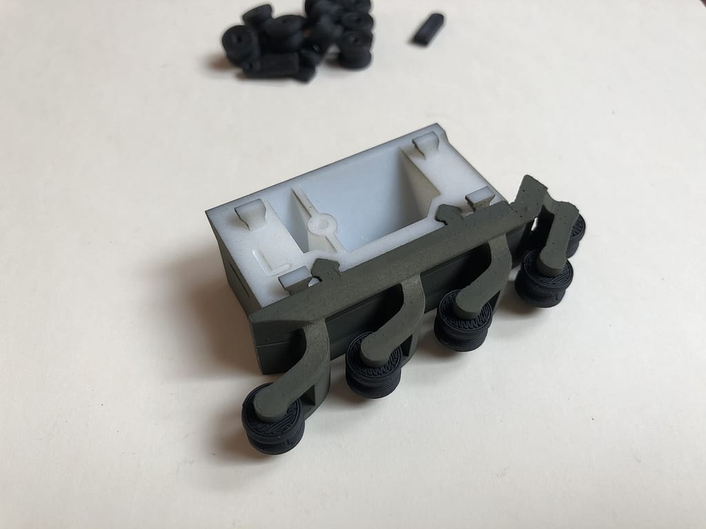
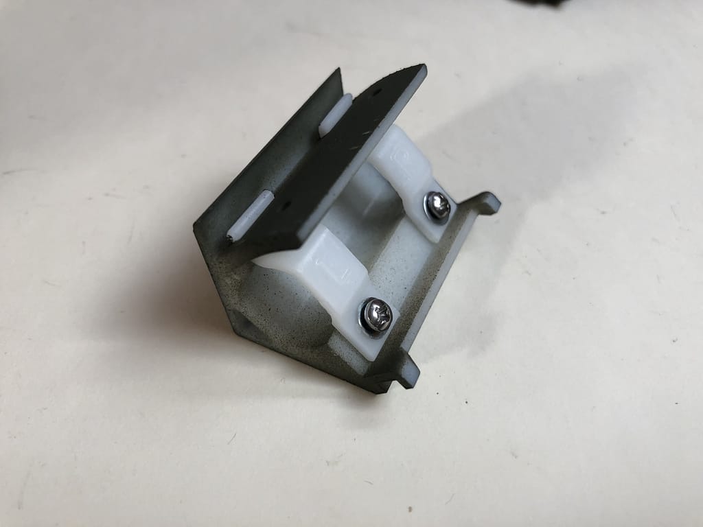
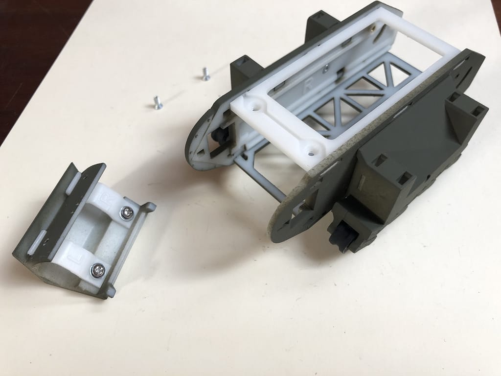
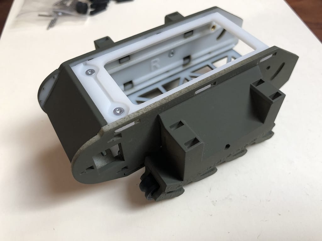
Step 6 – Attach Sponsons
For each side, push the sponson tabs into the holes of the side panel. Carefully push the sponson down to wedge the tabs into place
Screw in place using the Torx head screws (#2-28 x 1/4″).
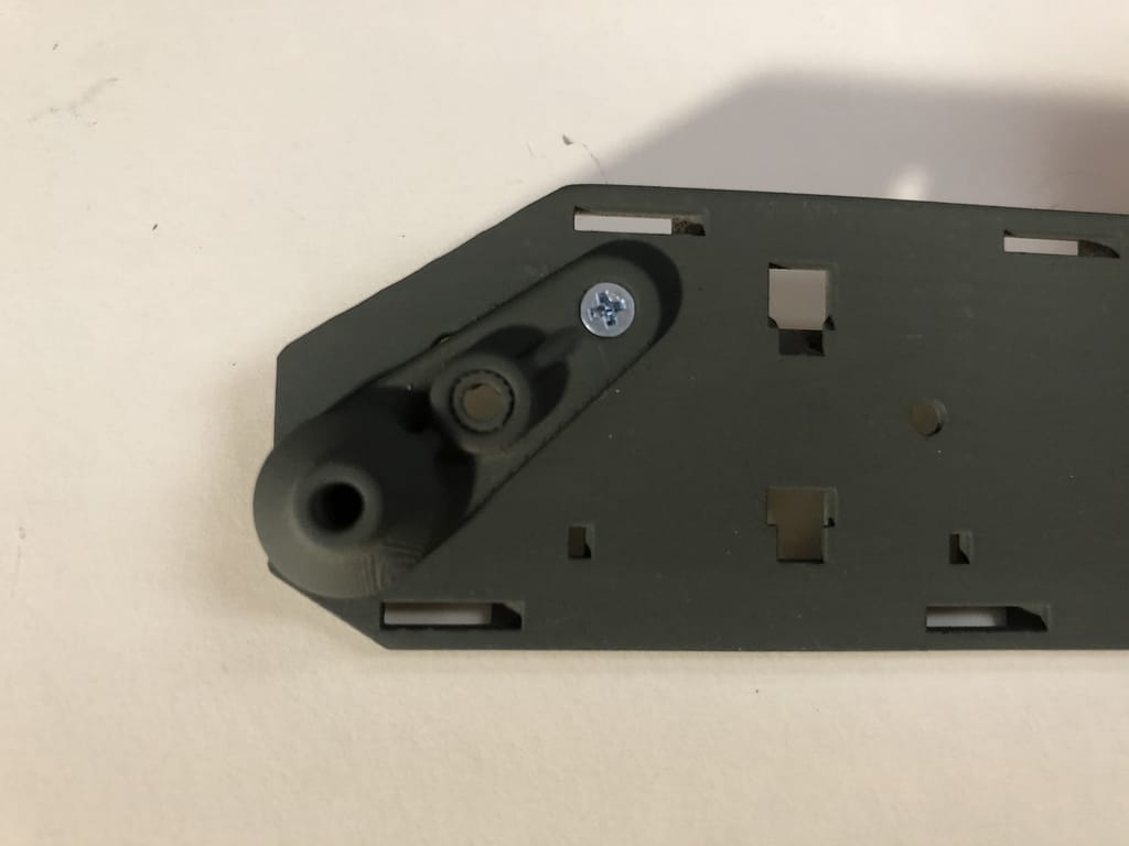
Step 7 – Attach Idler arm
Screw in the pivot point of the idler arm using the flathead Philips screw (#2-56 x 1/4″). Don’t over tighten this screw.
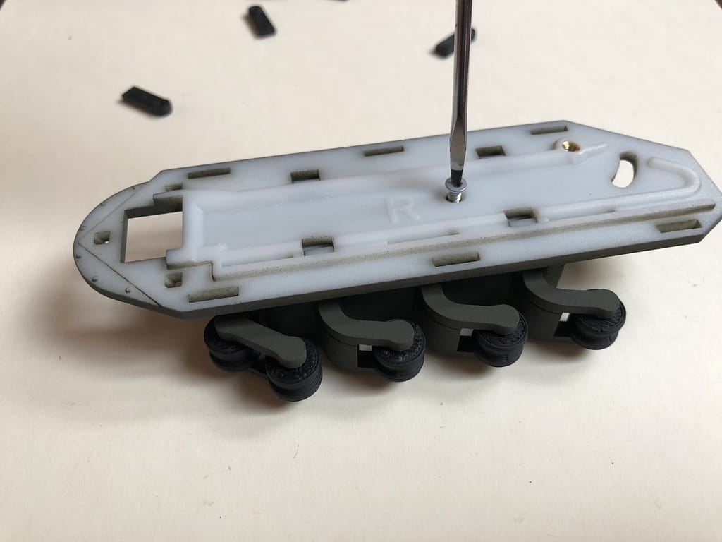
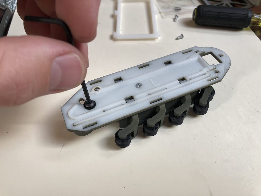
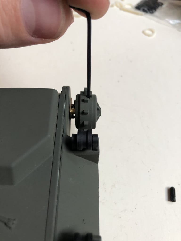
Step 8 – Adjust Idler arm
Screw in the adjustment screw of the idler arm, with matching washer, from the L or R marked side.
Use the shorter, black hex cap screw (M3-0.5 x 8mm). I recommend moving the idler arm all the way to the bottom position like in the image. Using new treads, this is usually already the perfect position.
Step 9 – Prep Nose Cone part 1
Insert the smaller square nuts (#2-56) into the slots in the nose cone.
Step 10 – Prep Nose Cone part 2
Place the L and R motor mounts and loosely screw them in using the silver button-head screws and washers of the same color.
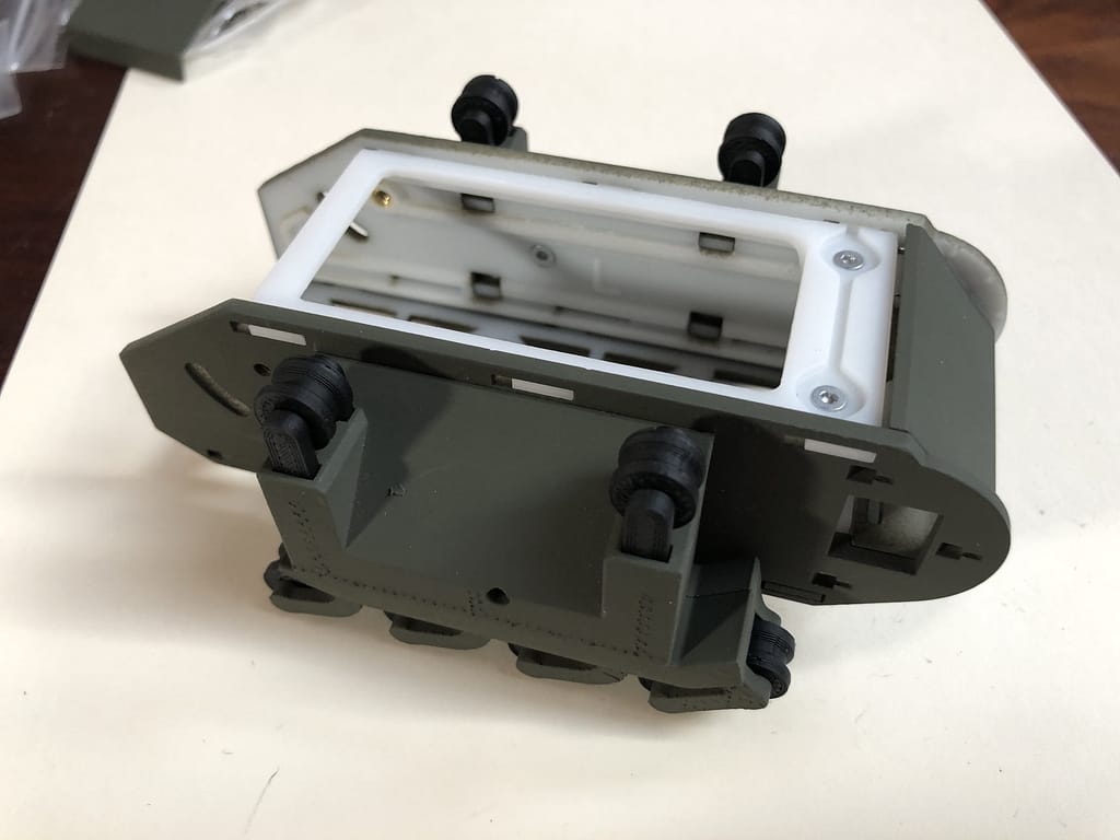
Step 11 – Attach Side Panels to Top/Bottom Panels
Insert the top and bottom panels into the side panels and slide them forward to wedge them into place.
Note which way up both panels go. For the bottom panel, make sure the painted side is facing down. For the top panel, make sure the screw countersinks are facing up.
Step 12 – Attach Nose Cone
Insert the two small hooks at the bottom of the nose cone into their intended slots on the bottom plate, and rotate the nosecone up into place. Screw the top panel to the nose cone using the Torx head screws.
Step 13 – Insert Roller Forks
Insert the top rollers with forks as shown
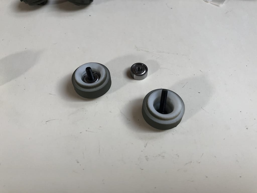
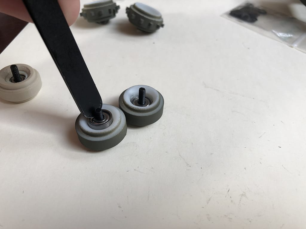
Step 14 – Insert Bearings into idler wheels
Place the longer, black hex cap screws into the idler wheels and push in a bearing over the screw using a screwdriver or tweezers
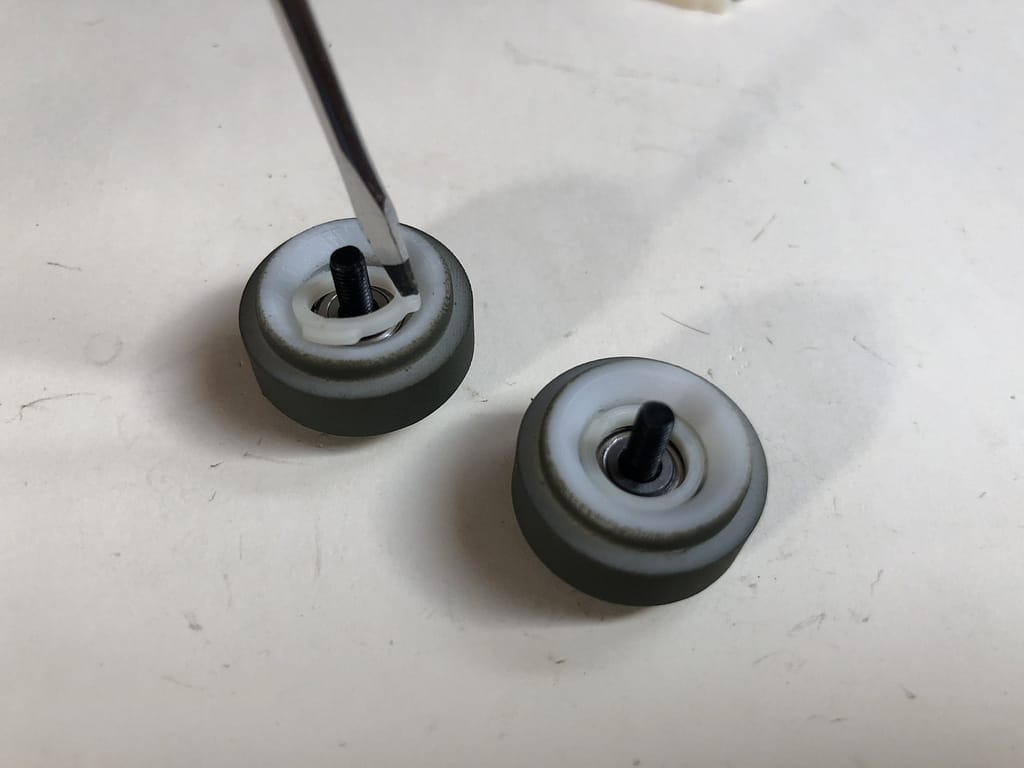
Step 15 – Insert Bearing Clips
Inside of the idler wheels, there are some small slots to hold the idler wheel clips into place. Locate them and gently push the flexible nylon pieces in using a screwdriver or tweezers
Step 16 – Attach Idler wheels
Insert the included 2mm hex key into the hole of the idler wheels to fasten them to the idler arms
Step 17 – Insert Motors
Push the motors in from the outside and tighten them down using the motor clamp screws.
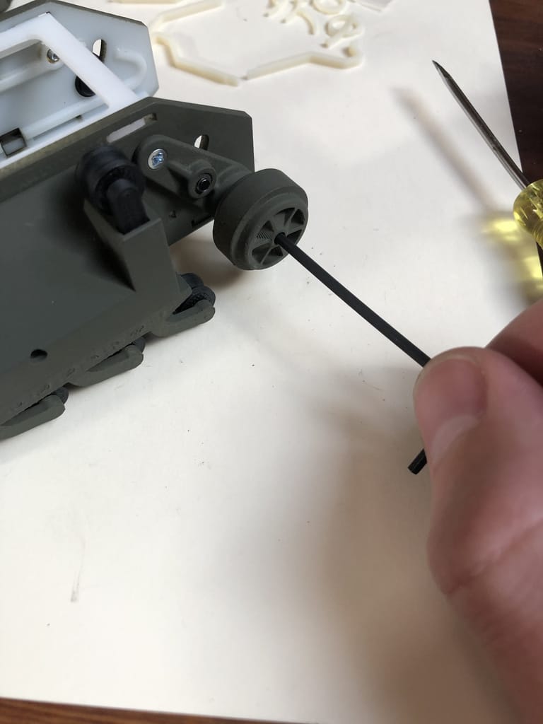
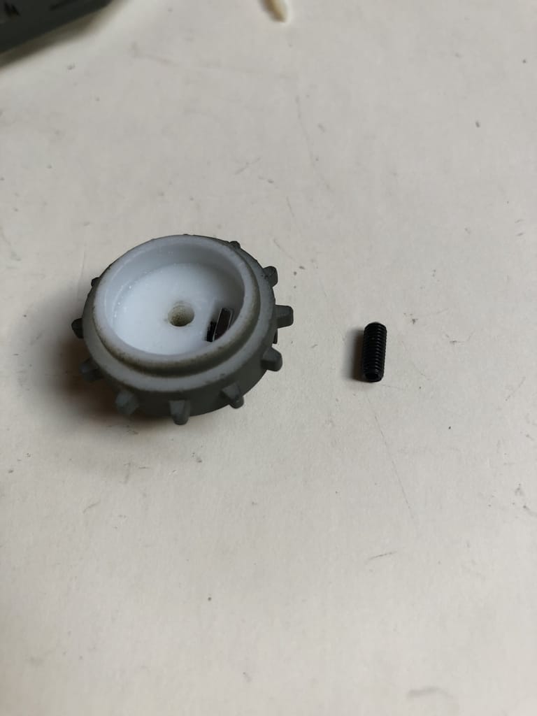
Step 18 – Prep Drive Wheels
Place the larger (M3-0.5mm) square nuts in the slots in the drive wheels and screw the black set screws into the side using the included 1.5mm hex key
Step 18 – Attach Drive Wheels
Slide the drive wheels onto the motor shafts and align them with the rollers. Tighten the set screw to fix them into place.
Step 19 – Glue Magnets
User some super glue to glue the included magnets into their designated holes of the gas/electric tops and phone mount top.
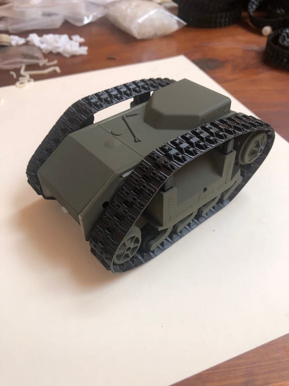
Step 20 – Add on 3DoT, Top and Tracks
Finally, slide in a 3DoT and connect the motors, Slip on the tracks and hook on the top!
Tip: slip the tracks over the drive wheels first.
Adjust the idler arm as necessary to tension the tracks. The loosest setting should be optimal on a new robot.
Chain Link Tracks
If you got the Legendary Kit from our kickstarter, check out the instructions to build the tracks here:
Next
Awesome! You built the Goliath and (probably) your first 3DoT robot! ?
Next, you can start controlling it from your phone and computer, or learn to program the robot yourself.
With most Humans for Robots products, you can scan the QR code on the printed circuit board using your phone camera to find instructions and downloads.
Try scanning the QR code on the bottom of the 3DoT Board or click this link to get started programming your 3DoT.
Click here if you just want to control Goliath using your phone.